Apr – Jul 2026 · Solo · C++, Python, ROS 2 Jazzy, Gazebo, SolidWorks, Raspberry Pi 5
This is a desktop-sized quadruped robot I designed, built, and programmed solo, from a SolidWorks assembly to a 3D-printed, hand-wired robot with 12 Feetech serial bus servos and a Raspberry Pi 5.
CAD
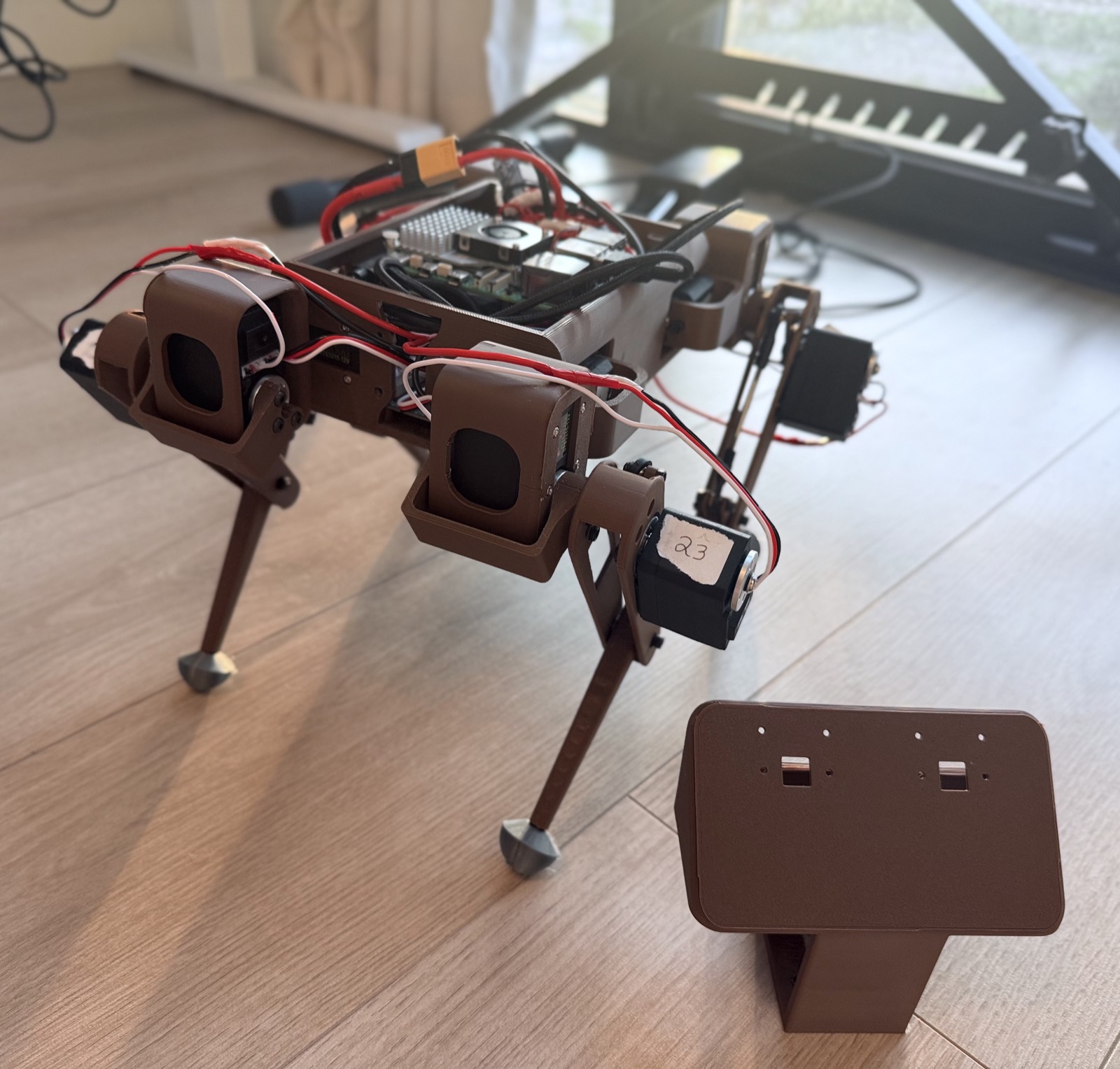
CAD is where this project spent most of its life. The initial version of the robot was designed for smaller motors and had two decks: a lower, shorter deck for the shoulder motors and the wiring, and an upper deck with the battery in the center, the Pi near the front, and a slightly tilted camera mount at the very front, with everything else filling the space around them.
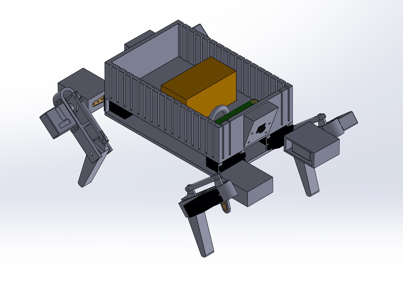
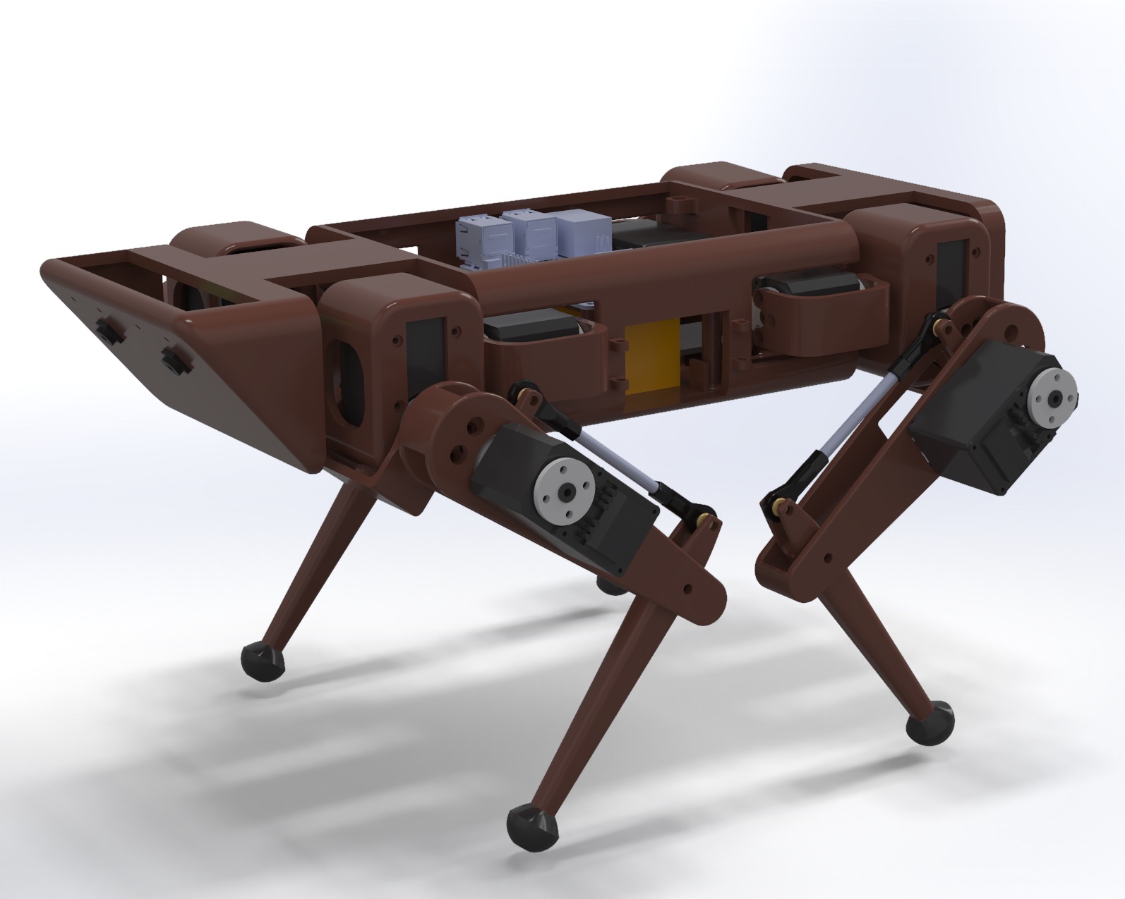
The first version looked like a “box on wheels,” so I gave it a more robust look. I also realized the mass was growing, so I redesigned it around Feetech STS3215s instead. The main body is a filleted rectangular extrude with a separate compartment where the battery slides in from the side, and the Pi sits above the battery. The head and the tail attach separately. This design has a single, shorter deck, which gives it a lower center of gravity, and this is the version I printed.
There were other intermediate designs, including one that housed all three motors inside the shoulder. That turned out not to be viable with the shape of standard servos, so the final design mounts the third (knee) motor at the hip and connects it to the knee with a parallel linkage (a turnbuckle).
Hardware & Electronics
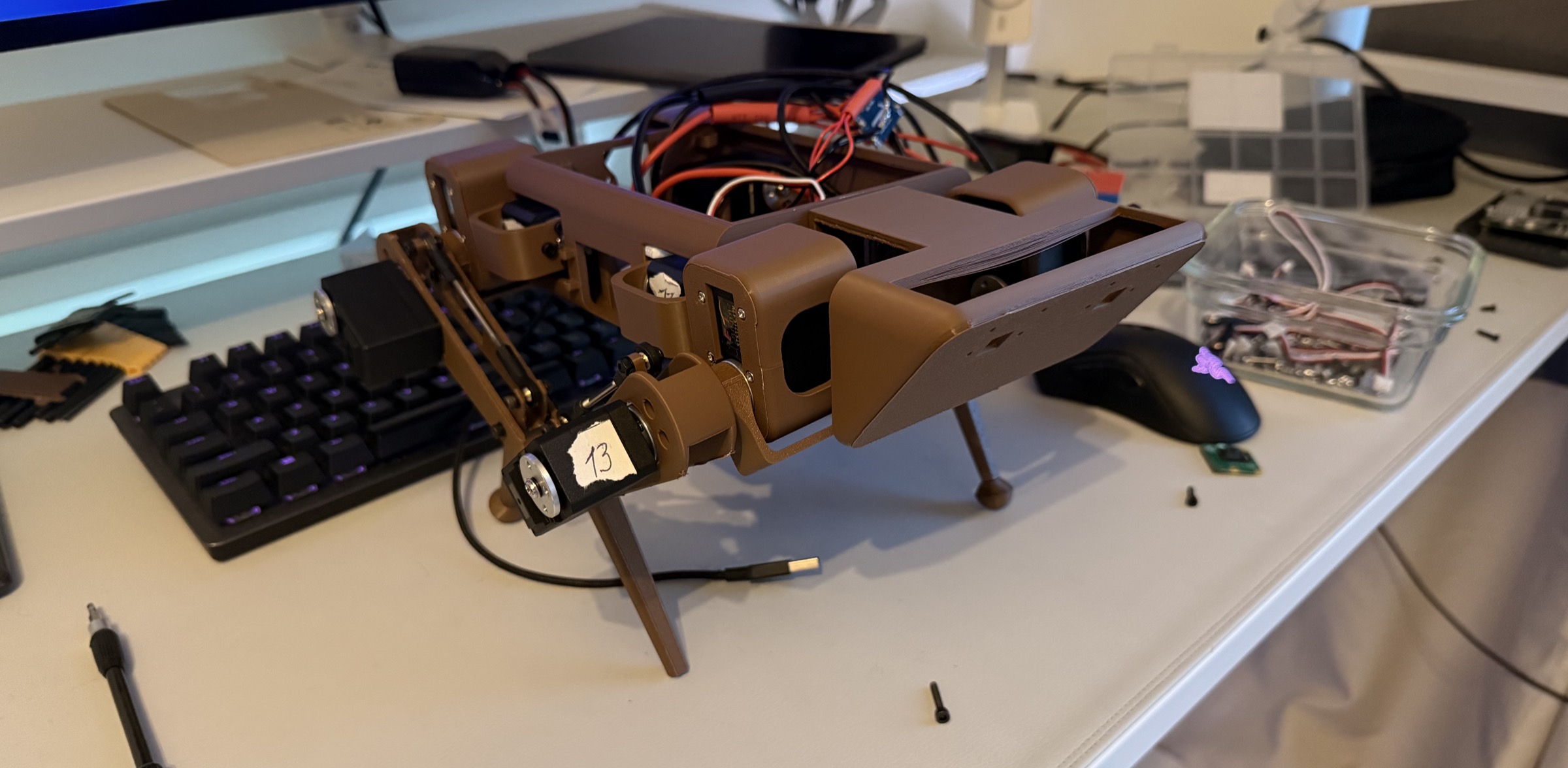
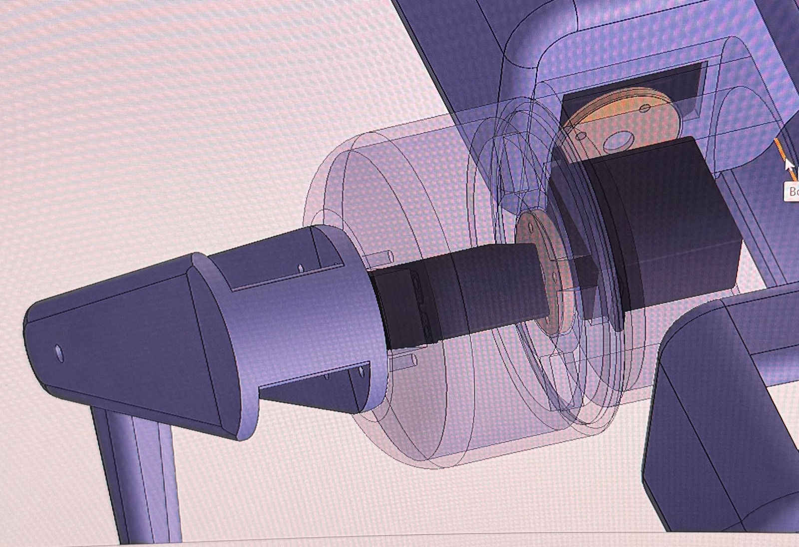
I 3D printed most of the robot’s parts on my Bambu P1S, using PLA+ for the body and TPU for the feet, since TPU has much more grip. I soldered most of the electronics myself. A 3S LiPo powered everything: a 14 AWG wire from the on/off switch split in a star into five branches, one for each leg’s three servos and one for the Pi. The servos got their power straight from the battery, while their signal lines were daisy-chained and connected to a Waveshare bus servo adapter. Sadly, I don’t have any electrical diagrams of it :(
Software
The software is a ROS 2 Jazzy workspace running on the Raspberry Pi 5. I split it into seven packages: the URDF robot model, a math library with the inverse kinematics and leg trajectories, the gait planner and commander nodes, a ros2_control hardware interface, and packages for simulation, teleop, and bringup. One launch argument switches between Gazebo and the real robot, so the same planner, commander, and controllers run in both.
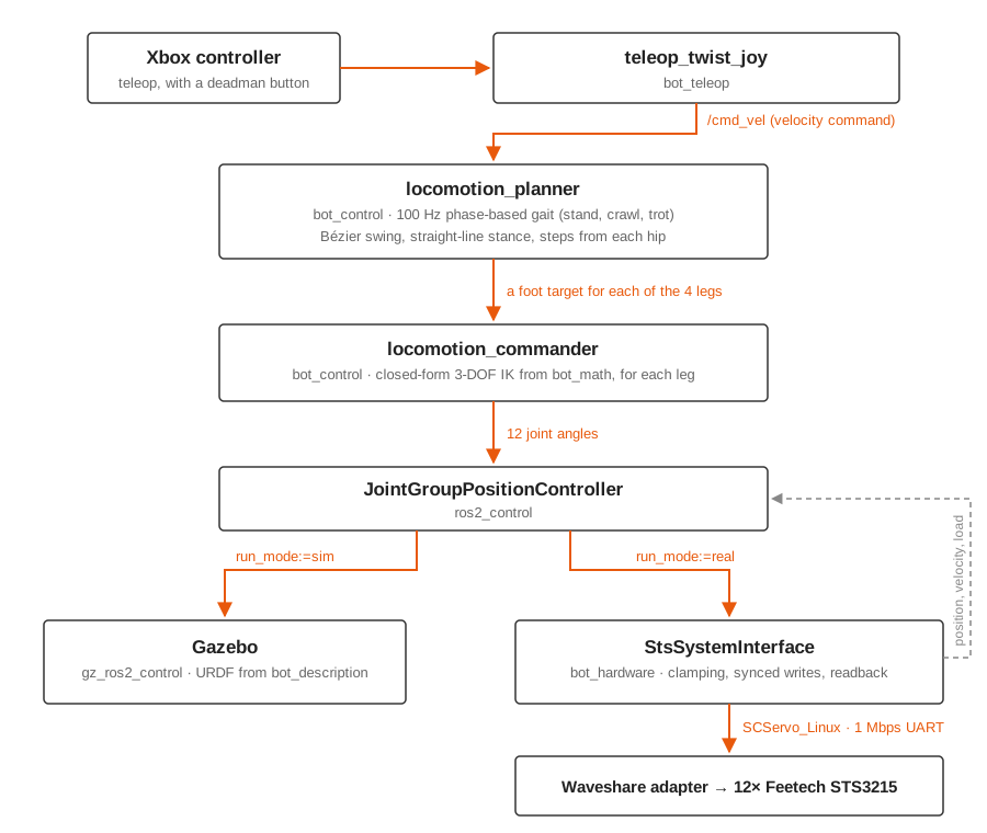
The gait planner is phase-based and runs at 100 Hz. It turns a body velocity command from the Xbox controller into a step for each foot, computed from that leg’s hip position, which is what lets the robot turn. Each foot follows a cubic Bézier curve in swing and a straight line in stance. The crawl uses a 0.75 duty factor with the legs a quarter cycle apart, and the trot uses 0.5 with the diagonal pairs in phase.
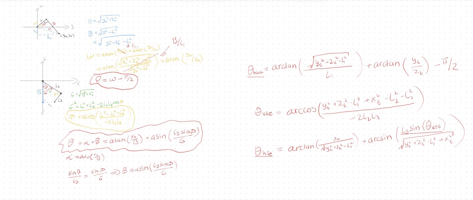
A second node runs closed-form inverse kinematics for each leg’s three joints (hip abduction, hip flexion, and knee) and sends the 12 joint angles to a position controller in ros2_control. I derived the equations geometrically on my iPad by drawing the leg at different angles. Targets that are out of reach, too close to the body, or at a singularity get clamped to the nearest safe pose.
For the real robot, I wrote a ros2_control hardware interface in C++ that drives all 12 servos on one 1 Mbps UART bus. Each write cycle clamps every command to its calibrated joint limits and a per-cycle velocity limit, then sends all 12 positions in a single synchronized bus write, and each read cycle pulls position, velocity, and load from every servo. On startup, it pings every servo and aborts if one is missing, seeds the first commands from the current pose so no joint snaps, and writes angle limits to EEPROM only when they differ, to save write cycles. The joint directions and zero offsets come from a calibration tool I wrote that reads the raw servo positions.
Before anything moved on the real robot, it walked in Gazebo. The URDF exported from SolidWorks runs with the Gazebo ros2_control plugin, so the simulated joints take exactly the same commands as the real ones.
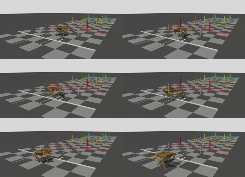
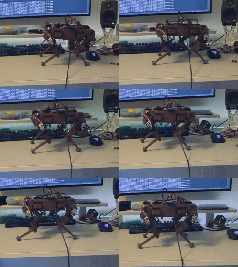
On the real robot, I teleoperated a crawl with an Xbox controller, forward, backward, and turning. It wasn’t smooth, and it never got to a trot. The gait runs open loop: the driver reads the servo feedback, but the planner doesn’t use it yet, so closing that loop was the next step. I paused the project in July 2026 to focus on classes. When I pick it back up, I’d start from a new CAD design with everything I learned here, and add an IMU and vision.